
GYROID
A gyroid structure is a distinct morphology that is triply periodic and consists of minimal iso-surfaces containing no straight lines.
The gyroid was discovered in 1970 by Alan Schoen, a NASA crystallographer interested in strong but light materials. Among its most curious properties was that, unlike other known surfaces at the time, the gyroid contains no straight lines or planar symmetry curves. In 1975, Bill Meeks discovered a 5-parameter family of embedded genus 3 triply periodic minimal surfaces.
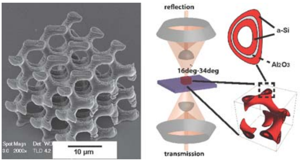
Photonic crystals were synthesized by deposition of a-Si/Al2O3 coatings onto a sacrificial polymer scaffold defined by two-photon lithography. We observed a 100% reflectance at 7.5 µm for single gyroids with a unit cell size of 4.5 µm, in agreement with the photonic bandgap position predicted from full-wave electromagnetic simulations, whereas the observed reflection peak shifted to 8 µm for a 5.5 µm unit cell size. This approach represents a simulation-fabrication-characterization platform to realize three dimensional gyroid photonic crystals with well-defined dimensions in real space and tailored properties in momentum space.


Three-dimensional photonic crystals offer opportunities to probe interesting photonic states such as bandgaps, Weyl points, well-controlled dislocations and defects. Combinations of morphologies and dielectric constants of materials can be used to achieve desired photonic states. Gyroid crystals have interesting three-dimensional morphologies defined as triply periodic body centered cubic crystals with minimal surfaces containing no straight lines. A single gyroid structure consists of iso-surfaces described by sin(x)cos(y) + sin(y)cos(z) + sin(z)cos(x) > u(x, y, z), where the surface is constrained by u(x, y, z). Gyroid structures exist in biological systems in nature. For example, self-organizing process of biological membranes forms gyroid photonic crystals that exhibit the iridescent colors of butterfly’s wings. Optical properties of gyroids could vary with tuning of u(x, y, z), unit cell size, spatial symmetry as well as refractive index contrast. Single gyroid photonic crystals, when designed with high refractive index and fill fraction, are predicted to possess among the widest complete three-dimensional bandgaps, making them interesting for potential device applications such as broadband filters and optical cavities.
Gyroid representation
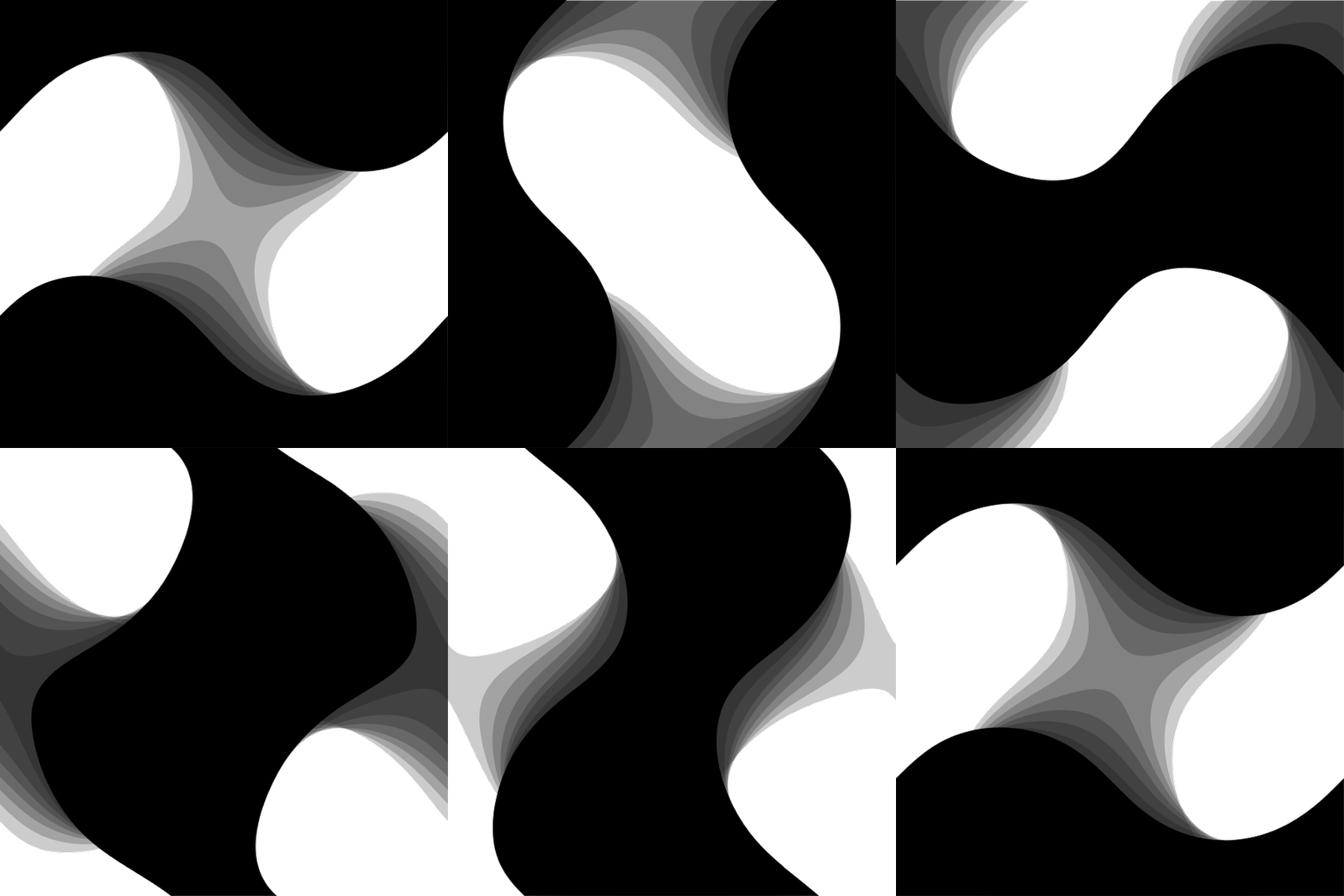
The minimal surface of the gyroid can be approximated by the level set equation, with the iso-value, h, set to h = 0. The parameter, a, is the unit cell length. By selecting alternative values for h between the limits (±1.413), the surface can be offset along its normal direction; beyond those limits the surface becomes disconnected, and ceases to exist for |h| > 1.5. Introducing an inequality enables the selection of the regions to either side of the shifted surface, producing the solid-network form. The solid-surface form is generated by selecting the region between two surfaces shifted along the surface normal to either side from their gyroid mid-surface (or alternatively using the inequality. The inequality produces two interwoven non-connected solid-network forms.


Solid finite element model


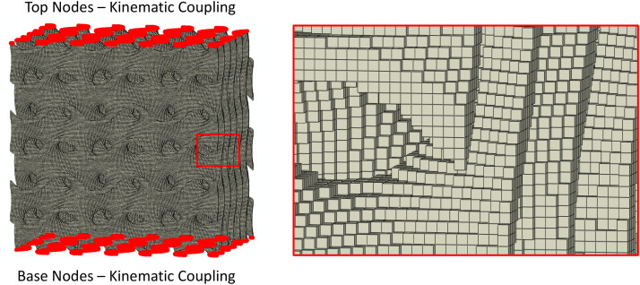
A voxel based finite element (FE) mesh with eight-node hexahedral elements was generated to approximate the solid-surface gyroid within a cubic bulk form. Firstly, a triangular mesh was constructed within Matlab using the iso-surface for h = 0. This mesh was copied and translated along the local normal to create the thickened solid-surface geometry and enclosed at the boundary edges. A voxelization function was then used to produce the voxel mesh. The voxel element size was set to target a minimum of 4 elements through the thickness direction.


One Comment
Nur Aqila
Hi Rajarshi Dey.
My name is Aqila. Kindly need your help since I have no one to ask. Currently, I am working to design primitive triply period minimal surfaces by varying the number of unit cells. But somehow, I have problems since my model that consist unit cells 2,4,6,8,… shows no wall. But for unit cells 1,3,5,7.. shows walls at the outside of the model (porous structure). Can you supervise me? Is there anything wrong with my script? Really need your help. Thank you and really appreciate for your reply.
% PRIMITIVE
L = linspace(-5,5,40)
[X,Y,Z]=meshgrid(L,L,L);
a=3; % no. unit of cell
x=a*pi.*X./(10/2);
y=a*pi.*Y./(10/2);
z=a*pi.*Z./(10/2);
cx=cos(x); cy=cos(y); cz=cos(z);
C1 =0.45;
pore_size = 1.5;
thickness = 1.5;
% % % —————————————————————————————————-
% Primitive
p= cx+cy+cz+(C1).*(cx.*cy+cy.*cz+cz.*cx)+pore_size;
c= -(p).^2+(thickness).^2;
%Plot
figure(1)
isosurface(X,Y,Z,c,0);
hold on;
figure(1)
isocaps(X,Y,Z,c,0);